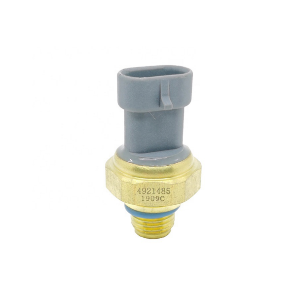
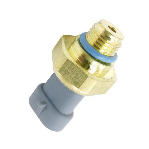
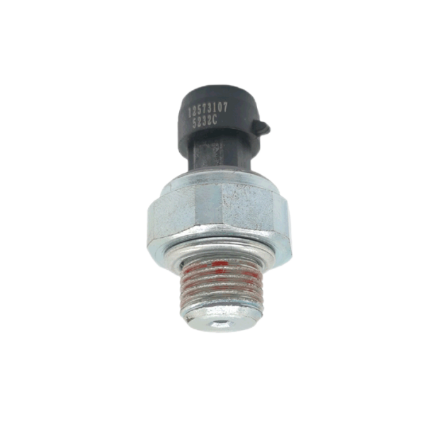
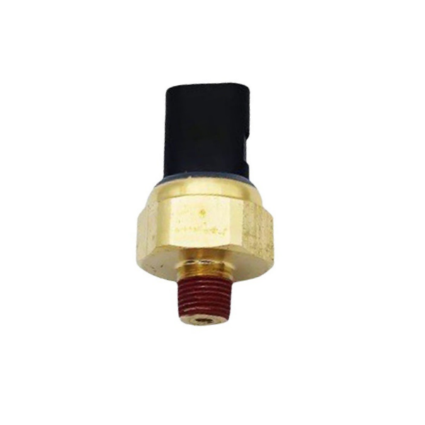
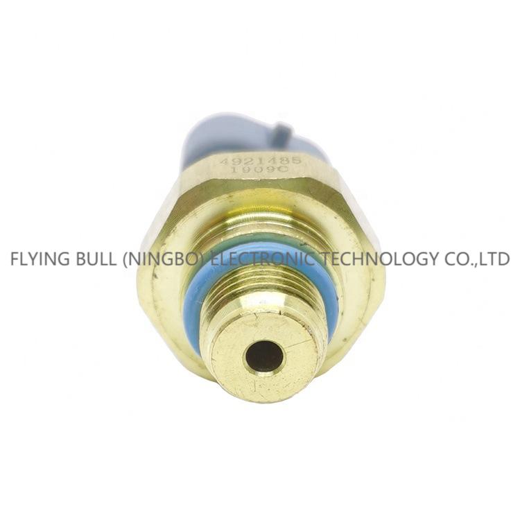
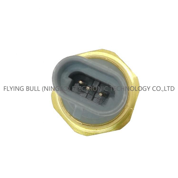
Suitable for Cummins L10 N14 M11 oil pressure sensor 4921485
Product introduction
Capacitive position sensor
1.Capacitive position sensor is a non-contact position sensor, which usually consists of three parts: detection area, protective layer and shell. They can measure the exact position of the target, but only the object. If the measured object is not conductive, it is still useful to measure its thickness or density.
2.When measuring a conductive object, the output signal has nothing to do with the material of the object, because for a capacitive displacement sensor, all conductors are the same electrode. This kind of sensor is mainly used in disk drive, semiconductor technology and high-precision industrial measurement, but it requires very high accuracy and frequency response. When used to measure non-conductors, capacitive position sensors are usually used to detect labels, coatings and measure the thickness of paper or film.
3.Capacitive position sensor was originally used to measure the linear displacement distance, ranging from several millimeters to several nanometers, and the measurement was completed by using the electrical characteristics of conductivity. The ability of an object to store charge is called capacitance. A common capacitor device for charge storage is a plate capacitor. The capacitance of plate capacitor is directly proportional to the electrode area and dielectric constant, and inversely proportional to the distance between electrodes. Therefore, when the distance between the electrodes changes, the capacitance also changes. In a word, capacitive position sensor uses this characteristic to complete position detection.
4.A typical capacitive position sensor includes two metal electrodes, with air as the dielectric. One electrode of the sensor is a metal plate, and the other electrode of the capacitor is composed of a conductive object to be detected. When a voltage is applied between conductor plates, an electric field is established between the plates, and the two plates store positive charges and negative charges respectively. Capacitive position sensor usually adopts AC voltage, which makes the charge on the plate change polarity regularly, so the change of target position can be detected by measuring the capacitance between the two plates.
5.The capacitance is determined by the distance between the plates, the dielectric constant of the dielectric and the distance between the plates. In most sensors, the area and dielectric constant of the electrode plate will not change, only the distance will affect the capacitance between the electrode and the target object. Therefore, the change of capacitance can show the target position. Through calibration, the output voltage signal of the sensor has a linear relationship with the distance between the detection board and the target. This is the sensitivity of the sensor. It reflects the ratio of output voltage change to position change. The unit is usually 1V/ micron, that is, the output voltage changes 1V every 100 microns.
6.When a voltage is applied to the detection space, a diffused electric field will be generated on the detected object. In order to reduce interference, a protective layer is added. It applies the same electromotive force at both ends of the detection area to prevent the electric field in the detection space from leaking. Conductors outside other detection areas will form an electric field with the protective layer and will not interfere with the electric field between the target and the detection area. Due to the protective layer, the electric field in the detection area is conical. The projected area of the electric field emitted by the detection electrode is 30% larger than the detection area. Therefore, the diameter area of the detected object must be at least 30% larger than the detection area of the sensor.
Product picture
Company details





Company advantage

Transportation

FAQ


