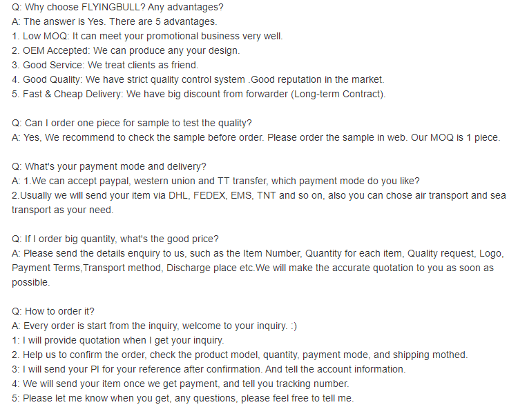
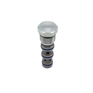
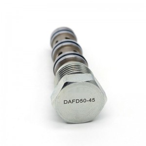
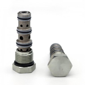
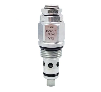
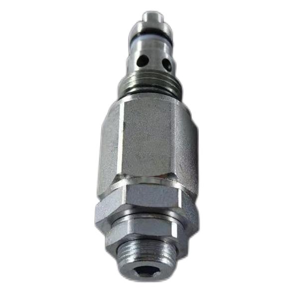
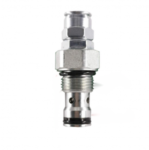
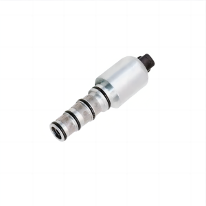
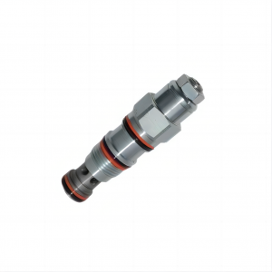
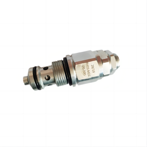
Mechanical and hydraulic plug-in collecting valve FD50-45
Details
Type (channel location):Three-way type
Functional action:Reversing type
Lining material:alloy steel
Sealing material:rubber
Temperature environment:normal atmospheric temperature
Flow direction:commutate
Optional accessories:coil
Applicable industries:accessory part
Type of drive:electromagnetism
Applicable medium:petroleum products
Product introduction
Diverter valve, also known as speed synchronization valve, is the general name of diverter valve, collecting valve, one-way diverter valve, one-way collecting valve and proportional diverter valve in hydraulic valves. Synchronous valve is mainly used in double-cylinder and multi-cylinder synchronous control hydraulic system. Usually, there are many methods to realize synchronous motion, but the synchronous control hydraulic system with shunt and collector valve-synchronous valve has many advantages, such as simple structure, low cost, easy manufacture and strong reliability, so the synchronous valve has been widely used in hydraulic system. The synchronization of the shunting and collecting valve is speed synchronization. When two or more cylinders bear different loads, the shunting and collecting valve can still ensure its synchronous movement.
Function
The function of the diverter valve is to supply the same flow (equal flow diversion) to two or more actuators from the same oil source in the hydraulic system, or supply the flow (proportional flow diversion) to two actuators according to a certain proportion, so as to keep the speed of the two actuators synchronous or proportional.
The function of the collecting valve is to collect the equal flow or proportional oil return from the two actuators, so as to realize the speed synchronization or proportional relationship between them. The shunting and collecting valve has the functions of both shunting and collecting valves.
The structural schematic diagram of the equivalent diverter valve can be regarded as a combination of two series pressure-reducing flow control valves. The valve adopts "flow-pressure difference-force" negative feedback, and uses two fixed orifices 1 and 2 with the same area as primary flow sensors to convert two load flows Q1 and Q2 into corresponding pressure differences δ P1 and δ P2 respectively. The pressure difference δ P1 and δ P2 representing the two load flows Q1 and Q2 are fed back to the common pressure reducing valve core 6 at the same time, and the pressure reducing valve core is driven to adjust the sizes of Q1 and Q2 to make them equal.
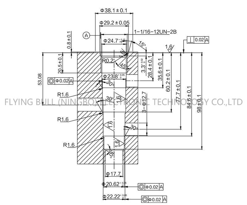
Product specification
Company details


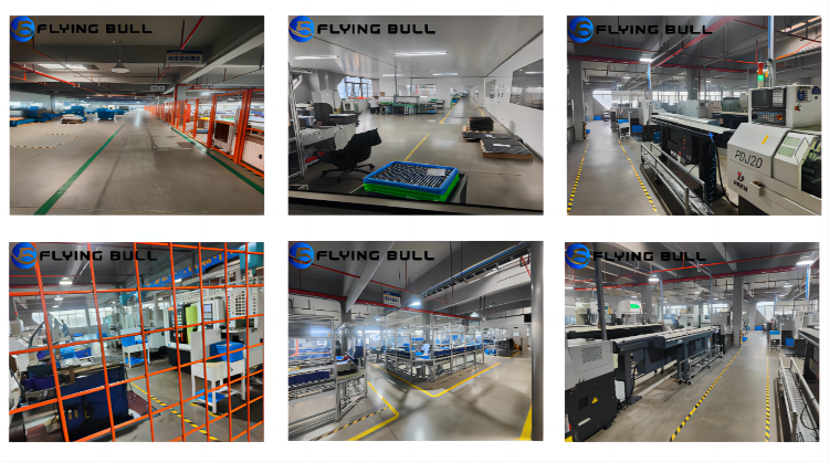

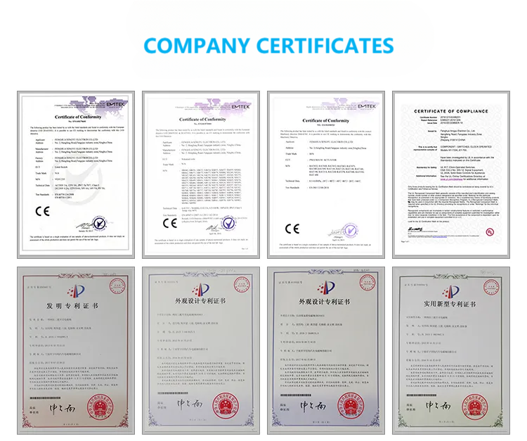
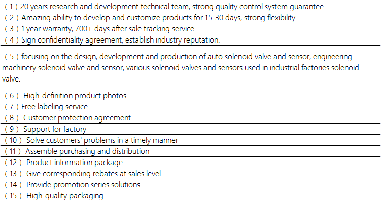
Company advantage
Transportation

FAQ
