Hydraulic solenoid valve 7200001740 LG958L LG968 wheel loader 4WG200 transmission solenoid valve 24V 12V 242137A1 0501313375 0260120025 0260120018 0501313369 0501313374


Video
Product Description
Suitable for Liugong Parts.
100% new and good quality.
Advantages:
1.Competitive price.
2.High quality guaranteed: one year. (OEM & ODM)
3.Specializing in engine parts for more than 20 years.
4.OEM or brand package as your require.
5.Save your time, save your Money.
6.One stop solution for the engine parts.
Main Products
Supply XCMG Parts,Caterpillar Parts,Perkins Parts,Weichai Deutz Parts,Doosan Parts,John Deere Parts,Kobelco Parts,SDLG Parts,Yuchai Parts,Shantui Parts,some can be equipped with famous brands like Doosan, Sany, KOMATSU, HITACHI, KOBELCO, LIUGONG,XCMG, Deutz, etc.
Important notes
★ When checking the transmission oil level, the engine should run at idle speed (about 1000/min), and the oil temperature should be at the normal operating temperature.
★ When the oil temperature is 40℃, the oil level should be between the middle scale line and the lower scale line of the oil scale.
★ When the oil temperature is 80℃, the oil level should be between the middle scale line and the upper scale line of the oil scale.
Note: When the engine stops running, the transmission oil level will basically rise, and the increase is related to the installation conditions of the transmission!
★Strictly follow the maintenance requirements to replace transmission oil and filter regularly.
★Make sure the control handle is in neutral before starting the engine.
★Release the parking brake every time before driving (release the brake)
★The engine and gearbox are fitted or separated. When the gearbox needs to be lifted, the torque converter should be avoided from falling off.
★When stopping, make sure the shift handle is in neutral.
★ Before the driver leaves the vehicle, use a stop block to ensure safety.
★ The speed of the trailer is strictly prohibited to exceed 10Km/h, and the distance of the trailer is strictly prohibited to exceed 10Km (helpless springs).
★Normal working oil temperature in 80-110℃, under heavy load, allow a short time to rise to 120℃
★ Pay special attention to the control oil pressure of gearbox. In use, when the gearbox is found to have abnormal phenomena, it should be stopped for inspection.
Note: When the vehicle has a problem and needs to be repaired by welding, the electrical plug on the EST computer controller must be unplugged (cut off the circuit to the computer controller), otherwise the computer controller may be burned by the shock current of the welding.
About This Item
4WG200 transmission Maintenance and repair of structural principle and replacement of solenoid valve
https://flyingbull.en.alibaba.com
https://www.alibaba.com/product-detail/4WG200-Transmission-Solenoid-Valve-7200001740-0501313375_1600201425441.html?spm=a2747.manage.0.0.37aa71d2IIUiXE
The ZF 4WG200 power shift gearbox consists of a torque converter and a fixed-shaft transmission with a multi-disc friction clutch. It has a choice of 3, 4, 5 or 6 forward gears and 3 backward gears. Especially suitable for wheel loader, bulldozer, grader, dump truck, forklift, truck crane, forklift, etc.
The ZF WG series power shift transmission provides all available technology to enable economical, efficient and safe operation. Four forward and three backward gears are usually selected, depending on the loader usage. For loaders that can run backwards and need to run backwards 30% of the working time, the gear subdivision of forward and backward gears is particularly important for economy and engine life. The 4WG200 gear we adopt is 4 in the front and 3 in the back, allowing the engine power to be 200kW and the highest engine speed to be 2800r/min, which is suitable for the matching use of Chinese 5 ton and 6 ton loaders.
https://flyingbull.en.alibaba.com
https://www.alibaba.com/product-detail/4WG200-Transmission-Solenoid-Valve-7200001740-0501313375_1600201425441.html?spm=a2747.manage.0.0.37aa71d2IIUiXE
Operation
1) Preparation and maintenance before driving
★ Before the transmission runs, be sure to add the appropriate amount of lubricating oil according to the specified lubricating oil specifications. When the gearbox is first filled with oil
★ It must be considered that the oil radiator, filter and connecting pipeline must be filled with oil. For this reason, the amount of lubricating oil added for the first time is more than the amount of lubricating oil for normal maintenance in the future.
★ Because the torque converter oil installed on the vehicle flows back to the gearbox through the oil radiator and oil pipe in the static state, the correct oil level should be controlled when the vehicle is in neutral, the engine is idle and the gearbox is at the normal heat balance temperature.
2)Driving and shifting
Make sure the shift handle is in neutral before starting the engine. For safety, before starting the engine, the parking brake should be in the braking state, so that the vehicle cannot start because the engine starts. After the engine starts, release the parking brake, select the driving direction and gear, and start the vehicle through the slow refueling door.
If the vehicle has stopped running, the engine is still running and the gearbox is in gear, then the engine will not stall. On a flat road, the vehicle may crawl because the engine is idling to generate some traction through the torque converter.
It is reasonable to put the parking brake in the braking state every time you stop. If you stop for a long time, the control handle must be shifted to neutral.
When the vehicle is moving, be sure to release the parking brake. We have learned from experience that it is difficult for the operator to immediately realize that when the torque converter is changing speed, the vehicle can overcome the braking torque and force it to drive even under fairly normal operation conditions because of the large output torque ratio of the torque converter。
3) Pause and stop
Because there is no rigid connection between the engine and the torque converter output shaft, so when the vehicle stops on a slope (uphill or downhill) and the driver intends to leave, in order to prevent the landslide of the vehicle, we suggest not only to stop the use of parking brakes but also to place a brake block under the wheel.
4) Drag
For the gearbox without auxiliary pump, the maximum speed of the trailer is 10km/h and the maximum drag distance is 10km.
These rules must be strictly observed, otherwise the gearbox will suffer damage due to insufficient fuel supply.
When the distance is longer, the faulty vehicle must be loaded on other vehicles.
Maintenance
1) Oil 4 WG-200 power shift transmission must be in strict accordance with the oil recommended by ZF TEML03 lubricating oil table or the loader instruction manual.
2) Check the oil level (once a week)
Park the vehicle on a flat spot, gearbox shift handle in neutral position "N" gearbox in operating temperature range, engine idle, about 1000 RPM /min
Remove the dipstick counterclockwise and wipe it clean
When the dipstick is inserted into the oil level tube and tightened, and then removed (at least two times)40C, the oil level should be between the lower scale "cold" and the middle scale
At 80C, the oil level should be between the upper scale "hot" and the middle scale
Checking the oil level of the cold car is only to ensure that the gearbox and the torque converter have sufficient circulating flow. The final standard to determine the oil level is to meet the oil level of the hot car.
3) Replace the oil and refueling amount
The first oil change must be made after the vehicle reaches 100 hours for the first time. After that, change the oil at least once every 1000 working hours or every year!
Oil changes must be made in accordance with the following requirements:
- Put the vehicle on a flat place, the gearbox at working temperature, remove the drain plug and seal ring, drain the old oil.
Note: When discharging oil, not only the transmission oil should be discharged clean, but also the oil of the torque converter and radiator should be discharged clean.
- Clean drain plug and casing sealing surface and install together with new sealing ring.
- Fuel according to ZF recommended lubricating oil gauge.
- Gearbox control handle in neutral position "N", start the engine and idle
- Oil to the upper mark of the "cold" oil zone
- Parking brake in safe position, all gears selected once and again check the oil level once, re-fuel as needed
At 40C, the oil level should be between the lower scale "cold" and the middle scale
At 80C, the oil level should be between the upper scale "hot" and the middle scale
4)Replace the oil filter
The ZF fine filter must be replaced with each oil change. Install, transport and store filters carefully!
Damaged oil filters are not allowed!
Filters must be installed as follows:
Apply a thin coat of oil to the sealing ring.
Press the filter in until it touches the sealing surface on the case, then tighten by hand about 1/3 to 1/2 turn. Then start the engine to fuel and check the oil level according to the above method. And check whether the filter is tight. Use your hands to tighten again if necessary.
2. Variable speed control oil circuit system
4WG200 transmission adopts electro-hydraulic pilot control, and its hydraulic control principle is shown in Figure 7. The oil circuit system is mainly composed of oil suction filter, variable speed pump, pipeline pressure oil filter and variable speed control valve. The torque converter and transmission oil are provided by the variable speed pump. The variable speed spring is the gear pump installed in the gearbox. It is directly driven by the engine through the force taking shaft, and its flow is Q=35 L /1000 RPM. The variable speed pump absorbs oil from the oil pan of the gearbox through the oil suction filter, and directly pumps the pressure oil into the pipeline pressure filter at the top of the box (oil filtration accuracy is 0.025mm, filter area is 500cm2). The filter is equipped with a pressure bypass valve (for safety protection). The oil comes out of the pipe filter and enters the variable speed control valve. The main pressure regulating valve of the variable speed control valve limits its working pressure (16-18bar) and then divides into two ways. The first way enters the solenoid valve as the pilot oil control shift valve through the pressure reducing valve (10bar). The other way through the pressure control valve into the gear valve.
The appearance of the variable speed control valve is shown in Figure 9, and the structure is shown in Figure 10 and 11.
It is composed of solenoid valve, pressure control valve, shift valve, etc. The variable speed control valve is fixed on the box (see Figure 2 and Figure 3). The function of the pressure control valve in the variable speed valve is to adjust the pressure boost characteristics of the clutch cylinder at the moment of shift, that is, the oil pressure will decrease instantaneously during shift, and then recover to 16-18bar(control pressure valve limit) after the shift is over (the clutch is engaged) This can reduce the impact of the shift and improve the smooth performance of the shift. The pressure oil through the gear valve enters the gear clutch directly.
The control pressure valve sends the spilled oil into the circulating oil circuit of the torque converter while limiting the maximum working oil pressure. In order to prevent the torque converter from being damaged, the inlet and outlet are equipped with safety valves, the opening pressure of the inlet safety valve is 8.5bar, and the opening pressure of the outlet safety valve is 5bar. The oil from the torque converter is cooled by the cooler and enters the gearbox lubricating oil road, and finally returns to the gearbox oil pan and enters the next recirculation.
The control circuit system is composed of computer controller, shift handle, electric control valve and connecting cable. The computer controller is the center of the transmission to achieve full automatic or semi-automatic control. When our ZL50G and ZL60G loaders are equipped with ZF transmission, the semi-automatic controller (EST-17) is used, as shown in Figure 12. The controller is installed in the right control box in the driver's room. The shift handle model is DWG-3, which is fixed on the steering column (see Figure 4 for the appearance). The solenoid valve is located in the variable speed control valve, and is fixed on the box.
The principle of the control circuit system is shown in Figure 13, and the control wiring is shown in Figure 14.
When the vehicle has a problem and needs to be repaired by electric welding, the electrical plug on the EST17 computer controller must be unplugged (cut off the circuit to the computer controller), otherwise the computer controller may be burned by the impact current of electric welding.
https://flyingbull.en.alibaba.com
3.Electronic control element fault detection
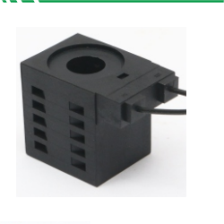
1)solenoid valve M1, M2, M3, M4, M5 measurement with a multimeter to measure the resistance of the solenoid valve. Unscrew the cable of the variable speed control valve, open the side cover of the variable speed control valve, loosen the plug of the solenoid valve, insert one end of the red line of the multimeter into the solenoid valve, the other end of the multimeter into the other end of the solenoid valve, test its resistance value, should be in 100+/-10Ω, not in the range that the solenoid valve is faulty and needs to be replaced, resistance value 0 indicates short circuit, o indicates open circuit.
2)Fault detection of gear selector
A. Methods to check whether the functions of each gear are normal
Use a multimeter to measure the circuit resistance. Connect one end of the multimeter pen with red line, and connect the other end with blue, green, black, yellow, gray, pink and purple respectively. Check the corresponding resistance. If the resistance value is o, the line is disconnected. Then hang the handle in turn forward two, three, four, backward one, two, E, four, neutral, pin, E, four. If the signals of all gears can meet the requirements of the signal diagram, the handle is normal.
B. Check whether KD function key of the handle is normal.
Connect one end of the multimeter pen with a red line and the other end with a purple line respectively to measure resistance. If the resistance is 0, it indicates that the line is connected. Release the KD key and the resistance is 0, it indicates that the line is disconnected. If the condition is reached, it indicates that the KD key of the handle functions normally.
If the KD key is pressed and the resistance is o, it indicates that the KD key switch cannot be switched on normally and the KD bond is abnormal.
3) Fault inspection of electric control box
A. Pull the plug off the electric control box and smell whether there is burning smell from the connector. If there is, the internal electrical components are burned out.
B. When the starting circuit is normal, the power supply is normal, the gearbox and other electrical components are normal, do not start the engine, hang in neutral, open the electric lock, the electric control box has two "tick, tick" sound, and then the solenoid valve "brush ~" ring, this is the electric control box on the solenoid valve detection. The electric control box can enter the detection state. The electric control box is normal.
C. Engine does not start, hang in neutral, open the electric lock. Step 1, step 2, Step 3 and step 4 respectively. Use a multimeter to test whether the electrical signals of each solenoid valve meet the requirements on the signal diagram. The corresponding voltage should be 24V.
D. If the requirements of the signal chart cannot be met, the discharge method can be used to judge. First check whether the shift handle is normal, then check whether each solenoid valve is normal, whether the speed sensor is normal, whether the ZF cable line plug connection and its circuit is normal, whether the host can supply power normally.


Product Display