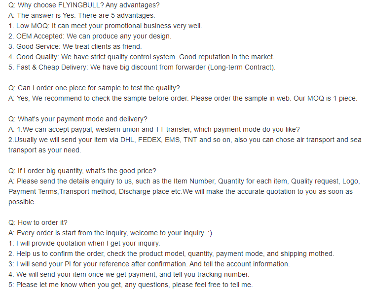
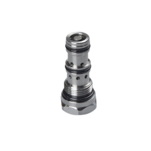
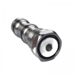
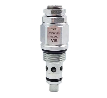
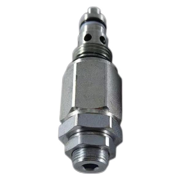
Hydraulic control check valve YDF10-00 for excavator
Details
Working temperature:normal atmospheric temperature
Type (channel location):Straight through type
Type of attachment:screw thread
Parts and accessories:accessory part
Flow direction:one-way
Type of drive:Hydraulic control
Pressure environment:Ordinary pressure
Product introduction
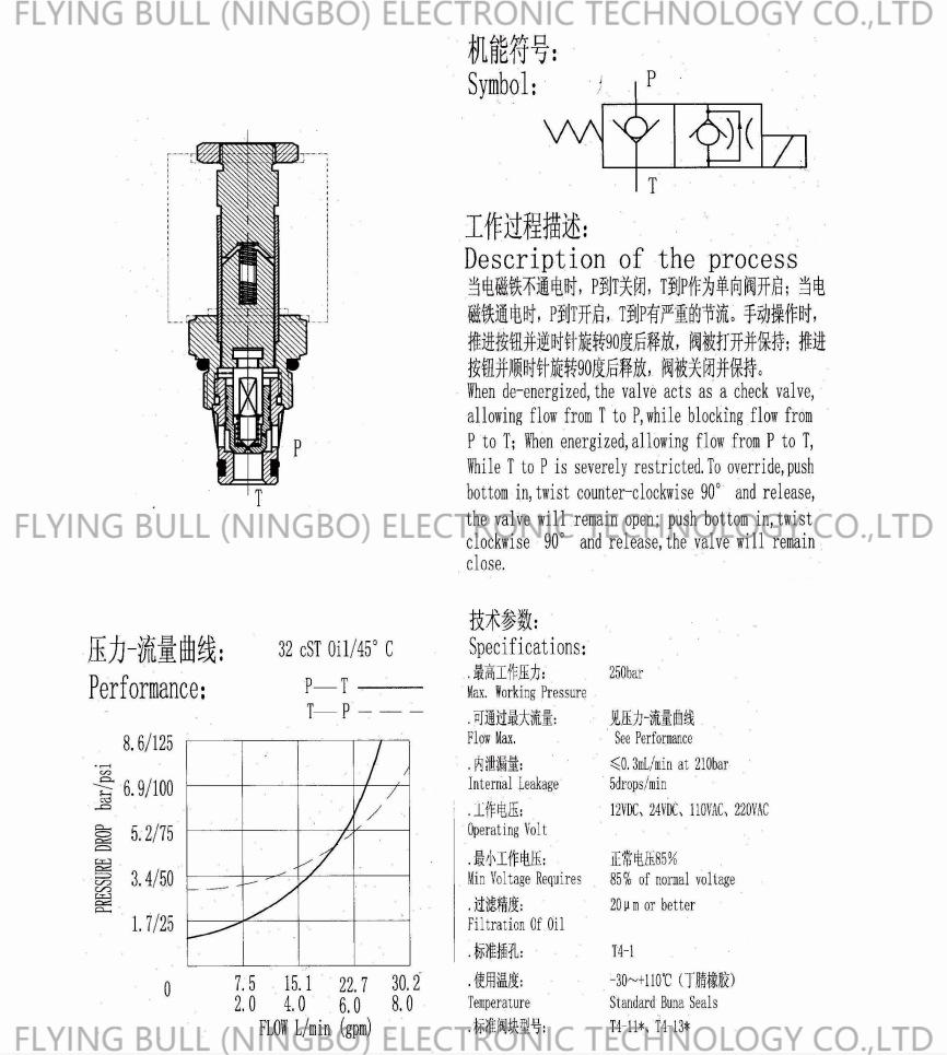
The solenoid valve mark indicates the front "several". You need to see the running state of this valve. You can say there are several. You will have a better understanding if there is a pneumatic seal mark. Symbolically, it means the square of the oil circuit board (with arrow symbol or T line). And the "several links" in the back means that there are several points on a square (the point crossing the arrow symbol line and the T line), which is several links. The meaning of symbol pictures is generally as follows:
1. The working part of the secondary relief valve is represented by squares, and several squares represent several "positions";
2. The arrow symbol in the box indicates that the oil passage is in the connected state, but the orientation of the arrow symbol does not necessarily indicate the specific direction of fluid and liquid;
3. The marked "T" or "T" in the box indicates that the channel is blocked;
4. If several sockets are connected to the outside of the box, it means several "connections";
5. General cartridge valve manufacturers use the letter P to indicate the air inlet/air inlet connected with the oil circuit or air supply provided by the system software; The pump oil/air return port connected between the valve and the oil return channel/air supply of the system software is denoted by T (sometimes O); The oil hole/air outlet connecting the valve with the actuator is indicated by a.b. Sometimes putting L on the symbol picture indicates that the oil hole is leaking;
6. Hydraulic directional valves have two or more working positions, one of which is the normalized position, that is, the position where the valve core is not subjected to control force. The negative correlation in the symbol picture is the normalization position of the three-position valve. The two-position valve calibrated by torsion spring takes the channel situation in the box close to the torsion spring as its normal position. When making the system diagram, the oil passage/air supply should generally be connected to the normalization position of the hydraulic valve.
Product specification
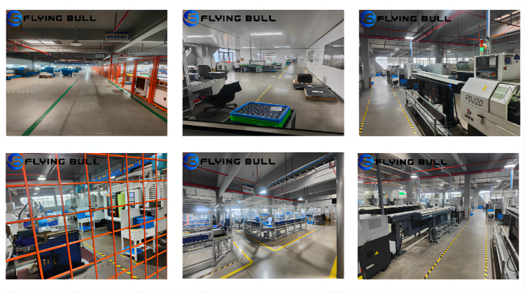
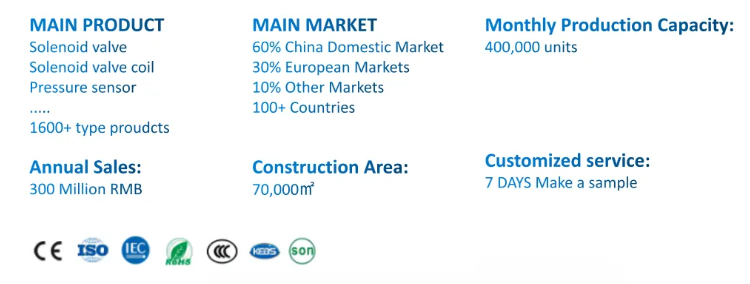
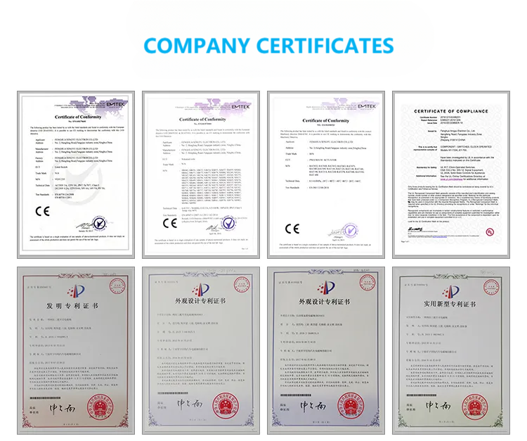
Company details



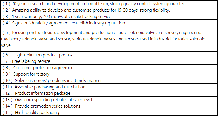
Company advantage
Transportation

FAQ
