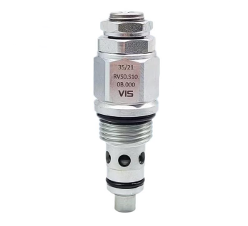
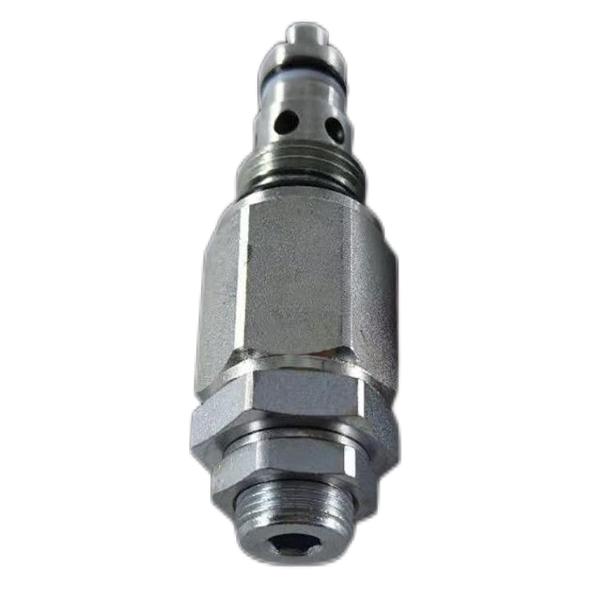
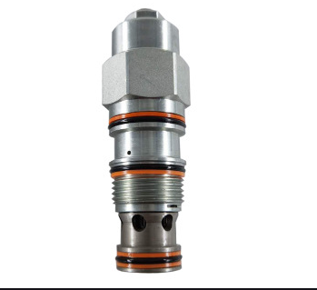
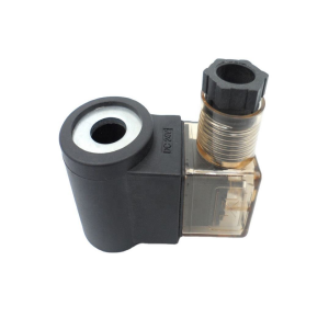
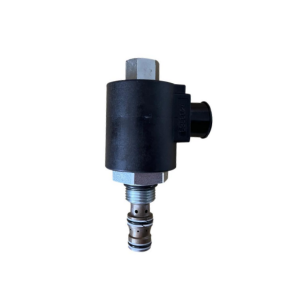
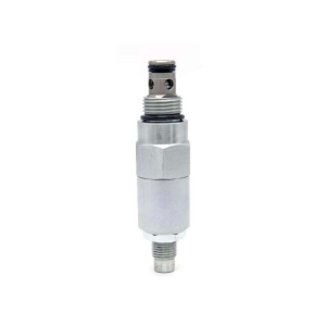
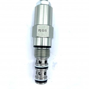
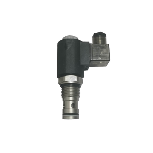
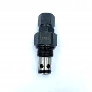
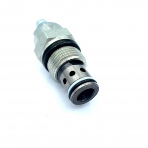
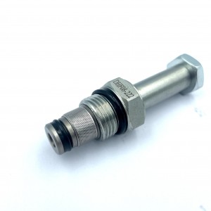
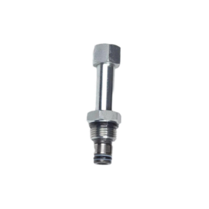
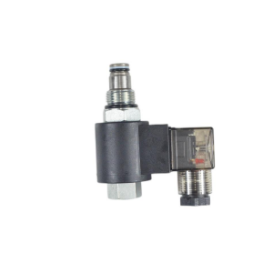
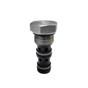
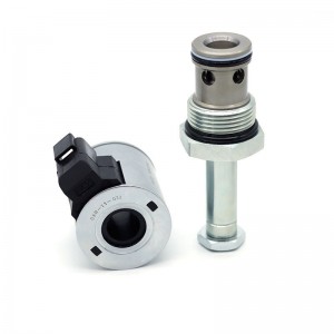
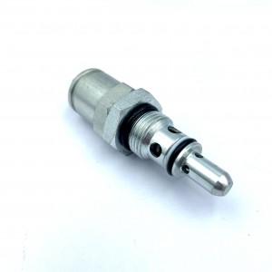
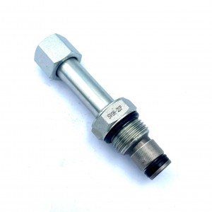
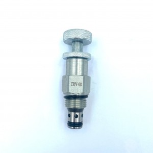
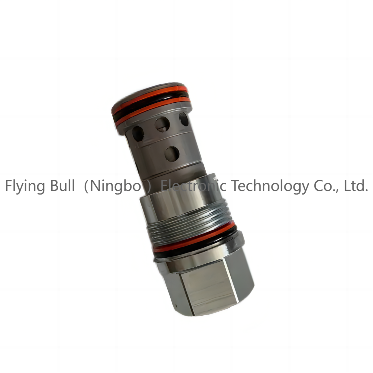
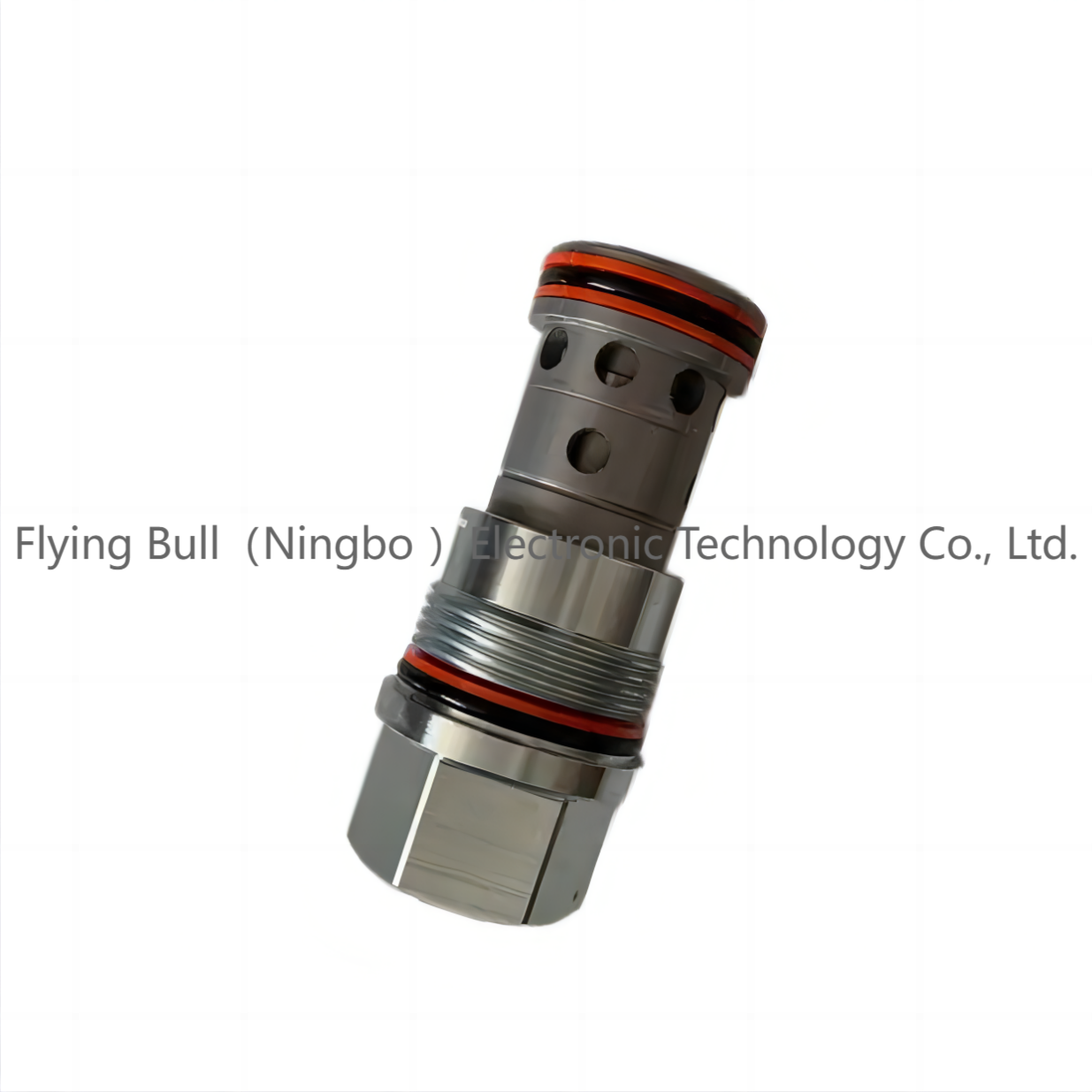
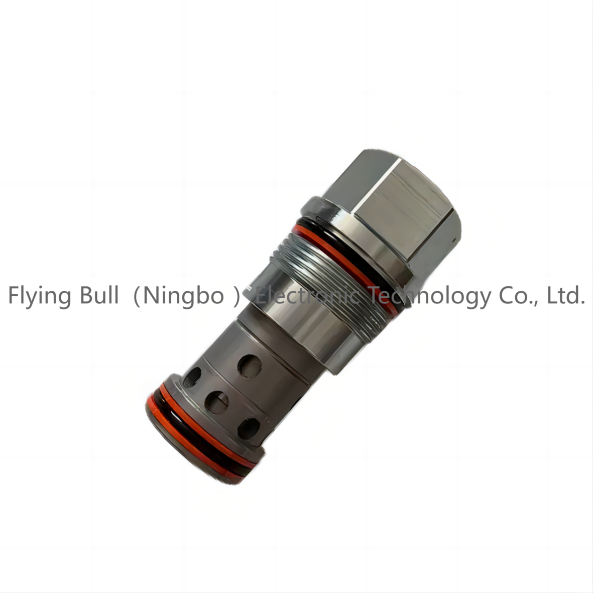
Hydraulic balance valve Excavator hydraulic cylinder spool CXHA-XAN
Details
Sealing material:Direct machining of valve body
Pressure environment:ordinary pressure
Temperature environment:one
Optional accessories:valve body
Type of drive:power-driven
Applicable medium:petroleum products
Points for attention
Balance valve structure and working principle
The hydraulic balance valve allows the oil to flow freely from port 2 to port 1. We can see from the structure diagram at the top of the figure below that when the oil pressure of port 2 is higher than that of port 1, the spool of the green part moves towards port 1 under the drive of liquid pressure, and the check valve is opened, and the oil can flow freely from port 2 to port 1.
The flow from port 1 to port 2 is blocked until the pressure of the pilot port reaches a certain value and the blue spool is moved to the left to open the valve port so that the oil can flow from port 1 to port 2.
The port closes when the pilot pressure is insufficient to open the blue spool. The flow from port 1 to port 2 is cut off.
The principle symbol of the balance valve is as follows;
Through the combination of the sequence valve and the balance valve in the figure below, many balance control schemes for large flow rates can be achieved. At the same time, if different balance valves are used in the pilot stage, a variety of different control combinations can be achieved. This kind of control scheme can greatly expand the design idea.
Balancing valve as a pressure limiting valve pilot valve parallel connection:
Different control processes are realized by parallel balancing valves with different pilot ratios. The two direct-acting balancing valves in Figure 4 comprise the pre-control. The negative load is the pilot valve that controls the differential pressure ratio of 2:1 is activated. When the load is positive, that is, when the pressure at the inlet is higher than the load pressure, the second pre-controlled balance valve will be activated, and the control pressure difference is higher than 10:1. In order to prevent the 10:1 balance valve from opening in the negative load area, there will be a pressure limiting valve R (actually an overflow valve). When the inlet pressure is high, the pressure limiting valve R opens, and the 10:1 balance valve receives the pilot pressure signal to open.
Different control performance can be obtained by adjusting the pressure limiting valve R.
Product specification
Company details





Company advantage
Transportation

FAQ
