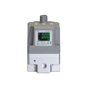
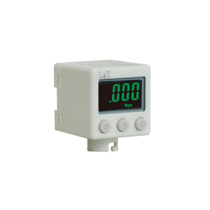
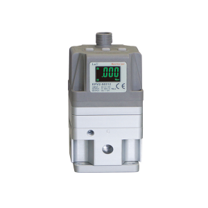
Air Filter Regulator EPV Series Electric proportional valve PVE1-1
Details
Min supply pressure: Set pressure +0.1MPa
Model Number:: PVE1-1 PVE1-3 PVE1-5
Max supply pressure: 10BAR
Set pressure range: 0.005~9MPa
Input signal current type: 4~20ma , 0~20MA
Input signal voltage type: DC0-5V , DC0-10V
Output signal switch output: NPN , PNP
Voltage: DC:24V 10%
Input impedance current type: 250Ω Less than
Input resistance voltage type: About6.5kΩ
Preset input: DC24Vtype:About4.7K
Analog output: "DC1-5V(Load impedance:1KΩmore than), DC4-20mA(Load impedance:250KΩLess than, Output accuracy within 6%(F.S)"
linear: 1%F.S
sluggish: 0.5%F.S
repeatability: 0.5%F.S
Temperature characteristic: 2%F.S
Pressure display accuracy: 2%F.S
Pressure display graduation: 1000graduation
ambient temperature: 0-50℃
the protection grades: IP65
Product introduction
Proportional valve characteristics
1) It can realize the stepless adjustment of pressure and speed, and avoid the impact phenomenon when the normally-on/off air valve changes direction.
2) Remote control and program control can be realized.
3) Compared with intermittent control, the system is simplified and components are greatly reduced.
4) Compared with the hydraulic proportional valve, it is small in size, light in weight, simple in structure and low in cost, but its response speed is much slower than that of the hydraulic system, and it is also sensitive to load changes.
5) Low power, less heat and low noise.
6) There will be no fire and no environmental pollution. Less affected by temperature changes.
The structure principle of electric proportional valve: when the input signal increases, the electromagnetic pilot valve 1 for air SUPply is reversed, while the electromagnetic pilot valve 7 for air exhaust is in the reset state, then the air supply pressure enters the pilot chamber 5 from the sup port through the valve 1, and the pressure in the pilot chamber rises, and the air pressure acts on the diaphragm 2, so that the air supply valve core 4 connected with the diaphragm 2 is opened and the exhaust valve core 3 is closed, resulting in output pressure. This output pressure is fed back to the control circuit 8 through the pressure sensor 6. Here, the output pressure is quickly compared with the target value until it is proportional to the input signal, so that the output pressure changes in proportion to the input signal.
1. In the controlled state, when the power supply is cut off due to power failure, this product can temporarily keep the secondary output.
2. The cable is connected to the machine with 4 cores, which may lead to misoperation when the monitor output (analog output and switch output) is not used, so avoid contact with other cables.
3. All products of our company are adjusted according to their own specifications when they are shipped, and random disassembly may lead to failure, so it is necessary to put an end to this behavior.
4. In order to avoid misoperation caused by noise, please take the following measures: ① Set a filter on the AC power cord to remove the power noise; ② This product and its wiring should be as far away from the strong magnetic environment such as the engine and power cord as possible to avoid the influence of noise; ③ Inductive loads (relays, solenoid valves, etc.) must be protected from load surge; ④ To avoid the influence of power fluctuation, please plug and unplug the connector after cutting off the power supply.
5. This cable device has a built-in locating groove. When locking, use a rotating external nut. Please do not rotate the plug-in body to prevent the connector from being damaged.
Product picture

Company details



Company advantage

Transportation

FAQ
