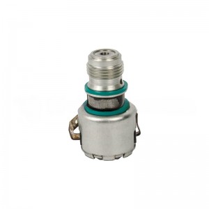
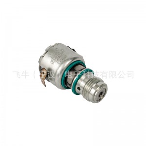
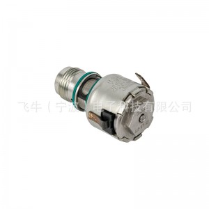
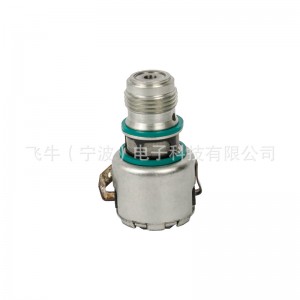
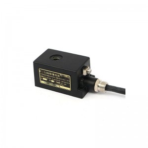
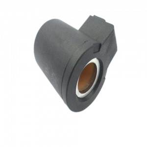
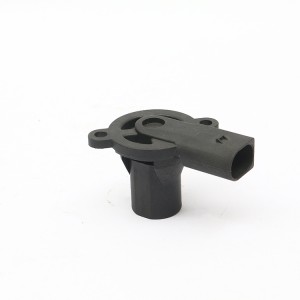
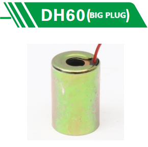
Cobo solenoid valve 3871711 for Cummins M11QSMISM engine
1. Power source; The motor is three-phase AC380V, 50Hz;; The control is two-phase AC220V, 50Hz.
(Special order AC220V, AC415V or AC660V. 60HZ)。
2. Working environment; Ordinary type is used in places without flammable, explosive and strongly corrosive media.
3. Protection level; IP55 (special order IP67).
4.1 Motor: YDF type is used for outdoor type, and YDF type three-phase asynchronous motor is used for flameproof type.
4.2 Deceleration mechanism: It consists of a pair of spur gears and a worm gear pair. The power of the motor is transmitted to the output shaft through the reduction mechanism.
4.3 Torque control mechanism: When a certain torque is applied to the output shaft, the worm rotates and generates axial displacement, which drives the crank, and the crank directly (or through the bump) drives the bracket to generate angular displacement. When the torque on the output shaft increases to the set torque, the displacement generated by the bracket makes the microswitch act, thus cutting off the power supply of the motor and stopping the motor. In this way, the output torque of the electric device can be controlled and the purpose of protecting the electric valve can be achieved.
4.4 Travel control mechanism:
The principle of decimal counter, also known as counter, is adopted, which has high control accuracy.
5 Its working principle is: a pair of bevel gears in the reduction box drives the transmission pinion, and then drives the stroke control mechanism to work. If the position of the stroke controller according to the opening and closing of the valve has been adjusted, when the controller rotates with the output shaft to the pre-adjusted position (number of turns), the cam will rotate 90, forcing the microswitch to act, cutting off the power supply of the motor and stopping the motor, thus realizing the control of the stroke (number of turns) of the electric device.
In order to control the valve with more turns, the cam can be adjusted to turn 180 or 270 and then the microswitch can be pressed to act.
5.1 Opening indicating mechanism: See Figure 8 for the structure. The input gear is driven by the unit gear of the counter. After deceleration, the indicator disc rotates simultaneously with the opening and closing process of the valve to indicate the on-off value of the valve, and the potentiometer shaft and the indicator disc rotate synchronously for remote communication indication. The number of turns can be changed by moving the number of turns adjusting gear. A microswitch and a cam are arranged in the opening indicating mechanism. When the electric device is running, the rotating cam periodically makes the microswitch move, and its frequency is one or two times when the output shaft rotates once, which can be used for flashing signals.


